

BOSCH REXROTH
R978017737
$443.00 USD
- BOSCH REXROTH
- Material:R978017737
- Model:4WE6E6X/EW110N9K4/62
Quantity in stock: 1
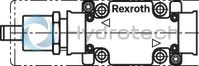
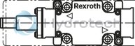
The Bosch Rexroth 4WE 6 E6X/EW110N9K4/62 (R978017737) is a high-performance industrial hydraulic valve designed for reliable control of oil flow direction in hydraulic systems. This direct-actuated spool valve features a Size 6 CETOP interface and comes with an electrical connection that includes a connector pole and PE according to EN standards. It operates with a supply voltage of 110 VAC and is capable of handling a maximum operating pressure of up to 350 bar. The valve offers flexibility in hydraulic applications with its max flow rates of DC 80 l/min and AC 60 l/min for different ports. Equipped with solenoid actuation, the Bosch Rexroth valve provides precise control over the start, stop, and direction of flow, with two switching positions facilitated by its electromagnets. The Type WE valve includes NBR seals compatible with various hydraulic fluids such as HL, HLP, HLPD, HVLP, HVLPD, and HFC. Its design conforms to CE standards under the Low Voltage Directive EU for electrical voltages greater than 50 VAC or greater than 75 VDC. This model also features options like auxiliary operating devices, spool position monitoring, and can be fitted with a throttle insert if required by operating conditions. Designed for subplate mounting, it follows porting patterns according to ISO standards and can be adjusted for three or four-way configurations. The high-power solenoid is optionally rotatable by 90 degrees providing flexibility in installation. Additionally, the Bosch Rexroth directional valve is engineered for energy efficiency; when equipped with detents (OF version), it allows the control spool to remain fixed in position without continuous current supply to the electromagnet. The product's robust construction ensures durability while allowing manual operation without magnet supply through auxiliary actuation. It is also available in versions that support soft switching behavior for reduced switching strokes during operation.
Size 6, symbol E, electrical with solenoid, 110-120 V AC
Industrial hydraulic valve in a high performance range. Reliable switching of the oil flow direction according to hydraulic symbol.
Unpacked Weight: 1.71 kg
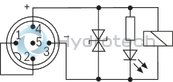
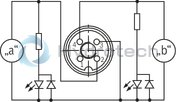
Directional valves type WE are solenoid-operated directional spool valves and can be used as electromagnetic components. They control the start, stop and direction of a flow.
The directional valves essentially consist of the housing (1), one or two electromagnets (2), the control spool (3) and the return springs (4).
In the de-energized state, the control spool (3) is held in the middle or initial position by the return springs (4) (except version “O”).
When the electromagnet (2) switching in oil is energized, the control spool (3) moves from its rest position to the desired end position. This releases the required flow direction according to the selected symbol.
After switching off the electromagnet (2), the control spool (3) is pushed back to the middle or initial position (except for valve with detent “OF” and valve without spring type “O”).
An auxiliary actuation (5) enables the valve to be switched manually without magnet supply.
The hydraulic system must be properly vented to ensure proper function.
Without spring return “O” (only possible with symbols A, C and D)
This version is a directional valve with two switching positions and two electromagnets without detent. The valve without spring return on the control spool (3) has no defined basic position when de-energized.
Without spring return with detent “OF” (only possible for symbols A, C and D)
This version is a directional valve with two switching positions and two electromagnets with detent. The control spool (3) is fixed in the respective switching position by the detents. During operation, the permanent current supply to the electromagnet can thus be omitted, which contributes to energy-efficient operation.
Version “.73...A12” (soft switching behavior)
The composition of the control spools and solenoids greatly reduces the number of switching strokes that occur when the valves are switched on or off. The switching strokes, measured as acceleration values a, can be reduced by approx. 85 % compared to the standard valve, depending on the version of the control spool (see “Acceleration values”).
Notices:
Pressure peaks in the drain line to two or more valves may cause unintentional control spool movements in the version with detent. It is recommended to lay separate return lines or to install a check valve in the drain line.
Due to the design principle, the valves are subject to internal leakage, which can increase during the service life.
Type 4WE 6 E6X/...E...

Throttle insert
The use of a throttle insert is required when, due to prevailing operating conditions, flows occur during the switching processes which exceed the performance limit of the valve.

| With locating pin ISO 8752-3x8-St: With fixing pin ISO 8752-3x8-St |
| Spool valve |
| Direct actuated |
| Maximum flow (AC) 60 l/min |
| Maximum operating pressure 350 bar |
| Maximum flow (DC) 80 l/min |
| Size 6 |
| Component series 6X |
| Data Sheet | Download Data Sheet |
| 3D CAD | Download 3D CAD |
| Manual | Download Manual |
| Manual | Download Manual |
| Manual | Download Manual |
| Manual | Download Manual |
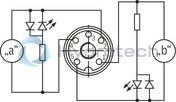
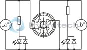
| Spool symbol | Symbol E |
| Max. pressure | 350 |
| Electrical connection description | Connector 3-pole (2 + PE) according to EN 175301-803 |
| Productgroup ID | 9,10,11,12,13,14 |
| Number of ports | 4 |
| Type of actuation | with solenoid actuation |
| Conformity description | CE – Low-Voltage Directive 2014/35/EU CSA approval according to CSA C22.2 No. 139-1982 |
| Size | 6 |
| Electrical connector | Connector 3-pole (2 + PE) |
| Max. flow | 60 |
| Type of connection | Subplate mounting |
| Connection diagram NFPA | NFPA T3.5.1 R2-2002 D03 |
| Size_CETOP | D03 |
| Connection diagram | ISO 4401-03-02-0-05 |
| Supply voltage | 110…120 VAC |
| Number of switching positions | 3 |
| Weight | 1.71 |
| Seals | NBR |
| Hydraulic fluid | HL,HLP,HLPD,HVLP,HVLPD,HFC |
| Conformity | CE |
|
01 |
02 |
03 |
04 |
05 |
06 |
07 |
08 |
09 |
10 |
11 |
12 |
13 |
14 |
15 |
16 |
17 |
18 |
19 |
20 |
21 |
||
|
WE |
6 |
6X |
/ |
E |
/ |
* |
|
01 |
3 main ports |
3 |
||||||||
|
4 main ports |
4 |
|||||||||
|
02 |
Directional valve |
WE |
||||||||
|
03 |
Size 6 |
6 |
||||||||
|
04 |
Symbols; for the possible version, see "Symbols/Circuit diagrams" |
|||||||||
|
05 |
Component series 60 … 69 (60 … 69: unchanged installation and connection dimensions) |
6X |
||||||||
|
06 |
With spring return |
no code |
||||||||
|
Without spring return |
O |
|||||||||
|
Without spring return with detent |
OF |
|||||||||
|
07 |
High-power solenoid, wet-pin, with detachable coil |
E |
||||||||
|
Electrical voltages |
||||||||||
|
08 |
For ordering code see "Electrical connections and available voltages" below. |
e.g. G24 |
||||||||
|
Manual override 1) |
||||||||||
|
09 |
Without manual override |
no code |
||||||||
|
With manual override |
N 3) |
|||||||||
|
With manual override "mushroom button" (small) |
N2 3) |
|||||||||
|
With lockable manual override "mushroom button" (small) |
N4 2; 3) |
|||||||||
|
With lockable manual override "mushroom button" (large) |
N5 2); 3; 4) |
|||||||||
|
With manual override "mushroom button" (large), not lockable |
N6 3; 4) |
|||||||||
|
With lockable manual override "nut" |
N72; 3) |
|||||||||
|
With concealed manual override (standard) |
N9 |
|||||||||
|
Corrosion resistance (outside) (for the availability, refer to the following table) |
||||||||||
|
10 |
None (valve housing primed) |
no code |
||||||||
|
Improved corrosion protection (240 h salt spray test according to EN ISO 9227) |
J3 |
|||||||||
|
High corrosion protection (720 h salt spray test according to EN ISO 9227) |
J5 |
|||||||||
|
Electrical connection |
||||||||||
|
11 |
Individual connection or central connection |
|||||||||
|
For ordering code see "Electrical connections and available voltages" below. |
e.g. K4 |
|||||||||
|
Spool position monitoring (For more information, see data sheet 24830) |
||||||||||
|
12 |
Without position switch |
no code |
||||||||
|
Inductive position switch type QM (valves with 2 spool positions) |
||||||||||
|
Monitored spool position "a" |
QMAG24 |
|||||||||
|
Monitored spool position "b" |
QMBG24 |
|||||||||
|
Monitored rest position |
QM0G24 |
|||||||||
|
Inductive position switch type QR (valves with 3 spool positions) |
||||||||||
|
Monitored rest position |
QM0G24 |
|||||||||
|
Monitored spool position "a" and "b" |
QRABG24E |
|||||||||
|
Inductive position switch type QS |
||||||||||
|
Monitored spool position "a" |
QSAG24W |
|||||||||
|
Monitored spool position "b" |
QSBG24W |
|||||||||
|
Monitored spool position "0" |
QS0G24W |
|||||||||
|
Monitored spool position "0" and "a" |
QS0AG24W |
|||||||||
|
Monitored spool position "0" and "b" |
QS0BG24W |
|||||||||
|
Monitored spool position "a" and "b" |
QSABG24W |
|||||||||
|
Switching time increase |
||||||||||
|
13 |
Without switching time increase |
no code |
||||||||
|
With switching time increase (only with direct voltage and only with version "N9" and symbol "73") |
A12 |
|||||||||
|
Throttle insert |
||||||||||
|
14 |
Without throttle insert (standard) |
no code |
||||||||
|
With throttle insert (when the admissible valve performance limit is exceeded, refer to "Performance limits"): |
||||||||||
|
Connection |
Throttle Ø in mm |
|||||||||
|
0,6 mm |
0,8 mm |
1,0 mm |
1,2 mm |
1,5 mm |
2,0 mm |
2,5 mm |
3,0 mm |
4,0 mm |
||
|
P |
= B06 |
= B08 |
= B10 |
= B12 |
= B15 |
= B20 |
= B25 |
= B30 |
= B40 |
|
|
A |
= H06 |
= H08 |
= H10 |
= H12 |
= H15 |
= H20 |
= H25 |
= H30 |
= H40 |
|
|
B |
= R06 |
= R08 |
= R10 |
= R12 |
= R15 |
= R20 |
= R25 |
= R30 |
= R40 |
|
|
A and B |
= N06 |
= N08 |
= N10 |
= N12 |
= N15 |
= N20 |
= N25 |
= N30 |
= N40 |
|
|
T |
= X06 |
= X08 |
= X10 |
= X12 |
= X15 |
= X20 |
= X25 |
= X30 |
= X40 |
|
|
Clamping length |
||||||||||
|
15 |
42 mm (standard) |
no code |
||||||||
|
22 mm |
Z |
|||||||||
|
Control spool play |
||||||||||
|
16 |
Standard (recommended) |
no code |
||||||||
|
Minimum (selection for reduced leakage values; higher oil cleanliness required) |
T06 |
|||||||||
|
Increased (selection with high temperature difference hydraulic fluid/environment; leads to higher internal leakage values) |
T12 |
|||||||||
|
Seal material (observe compatibility of seals with hydraulic fluid used, see "Technical data") |
||||||||||
|
17 |
NBR seals |
no code |
||||||||
|
FKM seals |
V |
|||||||||
|
Recommended for operation with HFC hydraulic fluids together with high temperatures |
MH |
|||||||||
|
Low-temperature version (only with version "Without manual override") |
MT |
|||||||||
|
18 |
Standard |
no code |
||||||||
|
Solenoid coil as approved component with UR marking according to UL 906, edition 1982 5) |
= UR |
|||||||||
|
Approval according to CSA C22.2 no. 139-1982 |
= CSA |
|||||||||
|
Porting pattern according to ANSI B93.9 6) |
= AN |
|||||||||
|
19 |
Without locating hole |
no code |
||||||||
|
With locating hole and locking pin ISO 8752-3x8-St |
/62 |
|||||||||
|
20 |
Standard |
no code |
||||||||
|
With reduced electric power consumption (only versions "G24" as well as "K4", "DL" and "DKL") |
SO407 |
|||||||||
|
21 |
Further details in the plain text |
* |
||||||||
| 1) |
Operation of the manual override only possible up to 50 bar [725 psi] tank pressure. Avoid damage to the bore of the manual override. (Special tool for the operation, separate order, material no. R900024943). If the manual override is blocked, operation of the opposite solenoid is to be excluded. The manual override cannot be allocated a safety function. |
| 2) | With tank pressures higher than 50 bar, it is not guaranteed that the valve remains in the position into which it was switched by the lockable manual override ("N4", "N5", "N7"). |
| 3) | Only direct voltage; not for version "= UR" |
| 4) | Only direct voltage; not for version "SO407" |
| 5) | Only for version "K4" with "G12", "G24" and "W110" |
| 6) |
With power supply to - solenoid "a", channel P is connected to a - solenoid "b", channel P is connected to B |
Available corrosion resistance
|
Electrical connection |
Manual override |
||||||||
|
"K4" |
"DL" |
"K40", "C4" |
|||||||
|
"G12" |
"G24" |
"G24" |
"G48" |
"G12" |
"G24" |
"G26" |
Ohne |
"N" |
|
|
"J3" |
✔ |
✔ |
✔ |
✔ |
- |
- |
- |
✔ |
✔ |
|
"J5" |
- |
- |
- |
- |
✔ |
✔ |
✔ |
✔ |
✔ |
Electrical connections and available voltages
(special voltages upon request)
DC voltage – individual connection
|
Connector |
Ordering code |
Electrical voltages |
Protection class according to DIN EN 60529 1) |
Protection class according to VDE 0580 |
|||||||||
|
12 V |
24 V |
26 V |
48 V |
96 V |
110 V |
125 V |
205 V |
220 V |
|||||
|
Ordering code |
|||||||||||||
|
G12 |
G24 |
G26 |
G48 |
G96 |
G110 |
G125 |
G205 |
G220 |
|||||
|
3-pole connector (2+PE) according to DIN EN 175301-803 |
Standard |
K4 |
✔ |
✔ |
- |
✔ |
✔ |
✔ |
✔ |
✔ |
✔ |
IP65 |
I 2) |
|
With potted-in plug base and sealing element |
K4K |
✔ |
✔ |
✔ |
- |
- |
- |
- |
- |
- |
IP65 |
I 2) |
|
|
Connector 2-pole, DT04-2PA (Deutsch type) |
K40 |
✔ |
✔ |
✔ |
- |
- |
- |
- |
- |
- |
IP65 |
III 3) |
|
|
Connector, 4-pole, M12x1 according to DIN EN 61076-2-101, with suppressor diode, coding A |
Pin assignment according to DESINA |
K72L |
- |
✔ |
- |
- |
- |
- |
- |
- |
- |
IP65 |
III 3) |
|
Standard |
K73L |
- |
✔ |
- |
- |
- |
- |
- |
- |
- |
IP65 |
III 3) |
|
|
Connector 2-pole (Junior-Timer type) |
Connector parallel to the valve axis |
C4 |
✔ |
✔ |
✔ |
- |
- |
- |
- |
- |
- |
IP65 |
III 3) |
|
Maximum admissible overvoltages according to DIN EN 60664-1:2008-01 (VDE 0110-1) (overvoltage category II): |
|||||||||||||
|
Nominal voltage UNom |
V |
12 |
24 |
26 |
48 |
96 |
110 |
125 |
205 |
220 |
|||
|
Rated current INom |
A |
2,5 |
1,25 |
1,17 |
0,66 |
0,33 |
0,25 |
0,17 |
0,16 |
0,14 |
|||
|
Maximum admissible switch-off overvoltage according to VDE 0580 |
V |
500 |
500 |
500 |
500 |
500 |
500 |
500 |
500 |
500 |
|||
|
Recommended interference protection circuit with 2 x mains voltage |
V |
24 |
48 |
52 |
96 |
192 |
220 |
250 |
410 |
440 |
|||
| 1) | Only with correctly mounted valve with a mating connector suitable for the protection class. |
| 2) | Protection class I with properly connected protective grounding conductor (PE) and valve mounting surface connected to the protective grounding conductor system. |
| 3) | With protection class III, a protective extra-low voltage with isolation transformer (PELV, SELV) is to be provided. |
Notice:
Solenoid valves induce voltage peaks during switch-off. In order to prevent electro-magnetic interference at the system and damage to the valve control, an interference protection circuit has to be provided on the system side. Alternatively, you can also select a connector with integrated interference protection circuit.
DC voltage - central connection
|
Connector |
Ordering code |
Electrical voltages |
Protection class according to DIN EN 60529 1) |
Protection class according to VDE 0580 |
|||||||
|
12 V |
24 V |
48 V |
96 V |
110 V |
125 V |
220 V |
|||||
|
Ordering code |
|||||||||||
|
G12 |
G24 |
G48 |
G96 |
G110 |
G125 |
G220 |
|||||
|
Cable gland, terminal area 6 … 12 mm |
With indicator light |
DL |
✔ |
✔ |
✔ |
✔ |
✔ |
✔ |
✔ |
IP65 |
I 2) |
|
With indicator light and interference protection circuit |
DL1 |
✔ |
✔ |
✔ |
✔ |
✔ |
✔ |
✔ |
IP65 |
I 2) |
|
|
Cable gland, threaded connection 1/2"-14 NPT |
With indicator light |
DAL |
✔ |
✔ |
- |
- |
- |
✔ |
- |
IP65 |
I 2) |
|
With indicator light and interference protection circuit |
DAL1 |
✔ |
✔ |
- |
- |
- |
✔ |
- |
IP65 |
I 2) |
|
|
7-pole connector (6+PE) according to DIN EN 175201-804 |
With indicator light |
DK6L |
- |
✔ |
✔ |
- |
✔ |
✔ |
✔ |
IP65 |
I 2) |
|
With indicator light and interference protection circuit |
DK6L1 |
- |
✔ |
✔ |
- |
✔ |
✔ |
✔ |
IP65 |
I 2) |
|
|
Connector according to ANSI/B93.55M-1981 (Brad Harrison Mini-Change) |
With indicator light, 3-pole |
DK23L |
- |
✔ |
- |
- |
- |
- |
- |
IP65 |
I 2) |
|
With indicator light, 5-pole |
DK25L |
- |
✔ |
- |
- |
- |
- |
- |
IP65 |
I 2) |
|
|
Connector, 4-pole, M12x1 according to DIN EN 61076-2-101 |
With indicator light |
DK24L |
- |
✔ |
- |
- |
- |
- |
- |
IP65 |
III 3) |
|
With indicator light and interference protection circuit |
DK24L1 |
- |
✔ |
- |
- |
- |
- |
- |
IP65 |
III 3) |
|
|
With indicator light and interference protection circuit |
DK35L |
- |
✔ |
- |
- |
- |
- |
- |
IP65 |
III 3) |
|
|
Maximum admissible overvoltages according to DIN EN 60664-1:2008-01 (VDE 0110-1) (overvoltage category II): |
|||||||||||
|
Nominal voltage UNom |
V |
12 |
24 |
48 |
96 |
110 |
125 |
220 |
|||
|
Rated current INom |
A |
2,5 |
1,25 |
0,66 |
0,33 |
0,25 |
0,17 |
0,14 |
|||
|
Maximum admissible switch-off overvoltage according to VDE 0580 |
V |
500 |
500 |
500 |
500 |
500 |
500 |
500 |
|||
|
Recommended interference protection circuit with 2 x mains voltage |
V |
24 |
48 |
96 |
192 |
220 |
250 |
440 |
|||
| 1) | Only with correctly mounted valve with a mating connector suitable for the protection class. |
| 2) | Protection class I with properly connected protective grounding conductor (PE) and valve mounting surface connected to the protective grounding conductor system. |
| 3) | With protection class III, a protective extra-low voltage with isolation transformer (PELV, SELV) is to be provided. |
Notice:
Solenoid valves induce voltage peaks during switch-off. In order to prevent electro-magnetic interference at the system and damage to the valve control, an interference protection circuit has to be provided on the system side. Alternatively, you can also select a connector with integrated interference protection circuit.
Alternating voltage – individual connection
|
Connector |
Ordering code |
Electrical voltages |
Protection class according to DIN EN 60529 1) |
Protection class according to VDE 0580 |
||||||||||
|
100 V 50/60 Hz |
100 V 50/60 Hz |
110 V 50/60 Hz |
110 V 50/60 Hz |
120 V 60 Hz |
120 V 60 Hz |
200 V 50 Hz |
200 V 50 Hz |
230 V 50/60 Hz |
230 V 50/60 Hz |
|||||
|
Ordering code |
||||||||||||||
|
G96 |
W110 |
G96 |
W110 |
G110 |
W110 |
G180 |
W200 |
G205 |
W230 |
|||||
|
3-pole connector (2+PE) according to DIN EN 175301-803 |
Standard |
K4 |
✔ |
✔ |
✔ |
✔ |
✔ |
✔ |
✔ |
✔ |
✔ |
✔ |
IP65 |
I 2) |
|
Rectifier required (see "Accessories") |
✔ |
✔ |
✔ |
- |
✔ |
- |
✔ |
- |
✔ |
- |
||||
|
Maximum admissible overvoltages according to DIN EN 60664-1:2008-01 (VDE 0110-1) (overvoltage category II): |
||||||||||||||
|
Nominal voltage UNom |
V |
100 |
100 |
110 |
110 |
120 |
120 |
200 |
200 |
230 |
230 |
|||
|
Rated current INom |
50?Hz |
A |
0,31 |
0,56 |
0,34 |
0,52 |
- |
- |
0,18 |
0,29 |
0,16 |
0,23 |
||
| 60?Hz |
A |
0,31 |
0,44 |
0,34 |
0,39 |
0,30 |
0,45 |
- |
- |
0,16 |
0,17 |
|||
|
Lower rated current |
50?Hz |
A |
- |
0,65 |
- |
0,6 |
- |
- |
- |
0,33 |
- |
0,27 |
||
| 60?Hz |
A |
- |
0,51 |
- |
0,45 |
- |
0,52 |
- |
- |
- |
0,2 |
|||
|
Upper rated current |
50?Hz |
A |
- |
0,9 |
- |
0,9 |
- |
- |
- |
0,6 |
- |
0,36 |
||
| 60?Hz |
A |
- |
0,9 |
- |
0,6 |
- |
0,9 |
- |
- |
- |
0,36 |
|||
|
Maximum admissible switch-off overvoltage according to VDE 0580 |
V |
500 |
500 |
500 |
500 |
500 |
500 |
500 |
500 |
500 |
500 |
|||
|
Recommended interference protection circuit with 2 x mains voltage |
V |
200 |
200 |
220 |
220 |
240 |
240 |
400 |
400 |
460 |
460 |
|||
| 1) | Only with correctly mounted valve with a mating connector suitable for the protection class. |
| 2) | Protection class I with properly connected protective grounding conductor (PE) and valve mounting surface connected to the protective grounding conductor system. |
Notices:
Solenoid valves induce voltage peaks during switch-off. In order to prevent electro-magnetic interference at the system and damage to the valve control, an interference protection circuit has to be provided on the system side. Alternatively, you can also select a connector with integrated interference protection circuit. Depending on the rated current INom, circuit breakers according to tripping characteristic "K" are to be provided.The tripping current must lie within a time interval of 0.6 s with 8 to 10 times the nominal power supply.
The required non-tripping current of the fuse must not fall below the "lower rated current" value (see preceding table). The maximum tripping current must not exceed the "upper rated current" value (see preceding table).
The temperature dependence of the tripping behavior of the circuit breakers has to be considered according to the manufacturer's specifications.
Alternating voltage – central connection
|
Connector |
Ordering code |
Electrical voltages |
Protection class according to DIN EN 60529 1) |
Protection class according to VDE 0580 |
||||||||
|
100?V?50/60?Hz |
110 V 50/60 Hz |
110 V 50/60 Hz |
120 V 60 Hz |
120 V 60 Hz |
200 V 50 Hz |
230 V 50/60 Hz |
230 V 50/60 Hz |
|||||
|
Ordering code |
||||||||||||
|
W100 |
W110R |
W110 |
W120R |
W110 |
W200 |
W230R |
W230 |
|||||
|
Cable gland, terminal area 6 … 12 mm |
With indicator light |
DL |
✔ |
✔ |
✔ |
✔ |
✔ |
✔ |
✔ |
✔ |
IP65 |
I 2) |
|
With indicator light and interference protection circuit |
DL1 |
✔ |
✔ |
✔ |
✔ |
✔ |
✔ |
✔ |
✔ |
IP65 |
I 2) |
|
|
With indicator light and interference protection circuit 3) |
DJL |
✔ |
- |
- |
- |
- |
✔ |
- |
- |
IP65 |
I 2) |
|
|
Cable gland, threaded connection 1/2"-14 NPT |
With indicator light |
DAL |
✔ |
✔ |
✔ |
✔ |
✔ |
- |
✔ |
✔ |
IP65 |
I 2) |
|
With indicator light and interference protection circuit |
DAL1 |
- |
✔ |
✔ |
✔ |
✔ |
- |
✔ |
✔ |
IP65 |
I 2) |
|
|
7-pole connector (6+PE) according to DIN EN 175201-804 |
With indicator light |
DK6L |
- |
✔ |
✔ |
✔ |
✔ |
- |
- |
- |
IP65 |
I 2) |
|
With indicator light and interference protection circuit |
DK6L1 |
- |
✔ |
✔ |
✔ |
✔ |
- |
- |
- |
IP65 |
I 2) |
|
|
Connector according to ANSI/B93.55M-1981 (Brad Harrison Mini-Change) |
With indicator light, 3-pole |
DK23L |
- |
✔ |
✔ |
✔ |
✔ |
- |
- |
- |
IP65 |
I 2) |
|
With indicator light, 5-pole |
DK25L |
- |
✔ |
✔ |
✔ |
✔ |
- |
- |
- |
IP65 |
I 2) |
|
|
Maximum admissible overvoltages according to DIN EN 60664-1:2008-01 (VDE 0110-1) (overvoltage category II): |
IP65 |
I 2) |
||||||||||
|
Nominal voltage UNom |
V |
100 |
110 |
110 |
120 |
120 |
200 |
230 |
230 |
|||
|
Rated current INom |
50?Hz |
A |
0,56 |
0,34 |
0,52 |
- |
- |
0,29 |
0,16 |
0,23 |
||
| 60?Hz |
A |
0,44 |
0,34 |
0,39 |
0,30 |
0,45 |
- |
0,16 |
0,17 |
|||
|
Lower rated current |
50?Hz |
A |
0,65 |
- |
0,6 |
- |
- |
0,33 |
- |
0,27 |
||
| 60?Hz |
A |
0,51 |
- |
0,45 |
- |
0,52 |
- |
- |
0,2 |
|||
|
Upper rated current |
50?Hz |
A |
0,9 |
- |
0,9 |
- |
- |
0,6 |
- |
0,36 |
||
| 60?Hz |
A |
0,9 |
- |
0,6 |
- |
0,9 |
- |
- |
0,36 |
|||
|
Maximum admissible switch-off overvoltage according to VDE 0580 |
V |
500 |
500 |
500 |
500 |
500 |
500 |
500 |
500 |
|||
|
Recommended interference protection circuit with 2 x mains voltage |
V |
200 |
220 |
220 |
220 |
240 |
400 |
460 |
460 |
|||
| 1) | Only with correctly mounted valve with a mating connector suitable for the protection class. |
| 2) | Protection class I with properly connected protective grounding conductor (PE) and valve mounting surface connected to the protective grounding conductor system. |
| 3) | Wire bridge between pin 2- and 4-. |
Notices:
Solenoid valves induce voltage peaks during switch-off. In order to prevent electro-magnetic interference at the system and damage to the valve control, an interference protection circuit has to be provided on the system side. Alternatively, you can also select a connector with integrated interference protection circuit. Depending on the rated current INom, circuit breakers according to tripping characteristic "K" are to be provided.The tripping current must lie within a time interval of 0.6 s with 8 to 10 times the nominal power supply.
The required non-tripping current of the fuse must not fall below the "lower rated current" value (see preceding table). The maximum tripping current must not exceed the "upper rated current" value (see preceding table).
The temperature dependence of the tripping behavior of the circuit breakers has to be considered according to the manufacturer's specifications.
general
|
Size |
6 | ||
|
Weight |
Valve with one solenoid |
kg |
1.45 |
|
Valve with two solenoids |
kg |
1.95 | |
|
Installation position |
any | ||
|
Ambient temperature range |
NBR seals |
°C |
-20 … +50 |
|
FKM seals |
°C |
-15 … +50 | |
|
Version for HFC hydraulic fluid |
°C |
-20 … +50 | |
|
Low-temperature version 1) |
°C |
-40 … +50 | |
|
Storage temperature range |
°C |
+5 … +40 | |
|
MTTFD values according to EN ISO 13849 2) |
Years |
300 | |
| 1) | For the use at low temperatures, see Project planning information |
| 2) | For further details, see data sheet 08012 |
hydraulic
|
Size |
6 | |||
|
Maximum operating pressure |
Port P |
Standard version |
bar |
350 |
|
Version "SO407" |
bar |
315 | ||
|
Port A |
Standard version |
bar |
350 | |
|
Version "SO407" |
bar |
315 | ||
|
Port B |
Standard version |
bar |
350 | |
|
Version "SO407" |
bar |
315 | ||
|
Port T |
Direct voltage 1) |
bar |
210 | |
|
AC voltage 1) |
bar |
160 | ||
|
Maximum flow |
Direct voltage |
Standard version |
l/min |
80 |
|
Version "SO407" |
l/min |
60 | ||
|
AC voltage |
l/min |
60 | ||
|
Flow cross-section (spool position 0) |
Symbol Q |
approx. 6 % of nominal cross-section | ||
|
Symbol W |
approx. 3 % of nominal cross-section | |||
|
Hydraulic fluid |
see table "Hydraulic fluid" | |||
|
Hydraulic fluid temperature range |
NBR seals |
°C |
-20 … +80 | |
|
FKM seals |
°C |
-15 … +80 | ||
|
Version for HFC hydraulic fluid |
°C |
-20 … +50 | ||
|
Low-temperature version 2) |
°C |
-40 … +50 | ||
|
Viscosity range |
mm²/s |
2.8 … 500 | ||
|
Maximum admissible degree of contamination of the hydraulic fluid, cleanliness class according to ISO 4406 (c) 3) |
Class 20/18/15 | |||
| 1) | With symbols A and B, port T must be used as leakage oil connection if the operating pressure exceeds the admissible tank pressure. |
| 2) | For the use at low temperatures, see Project planning information |
| 3) | The cleanliness classes specified for the components must be adhered to in hydraulic systems. Effective filtration prevents faults and simultaneously increases the life cycle of the components. For the selection of the filters, see www.boschrexroth.com/filter. |
|
Hydraulic fluid |
Classification |
Suitable sealing materials |
Standards |
Data sheet |
|
|
Mineral oils |
HL, HLP, HLPD, HVLP, HVLPD |
NBR, FKM |
DIN 51524 |
90220 |
|
|
Bio-degradable |
Insoluble in water |
HETG |
FKM |
ISO 15380 |
90221 |
|
HEES |
FKM |
||||
|
Soluble in water |
HEPG |
FKM |
ISO 15380 |
||
|
Flame-resistant |
Water-free |
HFDU (glycol base) |
FKM |
ISO 12922 |
90222 |
|
HFDU (ester base) |
FKM |
||||
|
HFDR |
FKM |
||||
|
Containing water |
HFC (Fuchs: Hydrotherm 46M, Renosafe 500; |
NBR |
ISO 12922 |
90223 |
|
|
Important information on hydraulic fluids: For more information and data on the use of other hydraulicfluids, please refer to the data sheets above or contact us. There may be limitations regarding the technical valve data (temperature, pressure range, life cycle, maintenance intervals, etc.). The ignition temperature of the hydraulic fluid used must be 50 K higher than the maximum surface temperature. Bio-degradable and flame-resistant – containing water: If components with galvanic zinc coating (e.g. version "J3" or "J5") or parts containing zinc are used, small amounts of dissolved zinc may get into the hydraulic system and cause accelerated aging of the hydraulic fluid. Zinc soap may form as a chemical reaction product, which may clog filters, nozzles and solenoid valves - particularly in connection with local heat input. Flame-resistant - containing water: Due to increased cavitation tendency with HFC hydraulic fluids, the life cycle of the component may be reduced by up to 30% as compared to the use with mineral oil HLP. In order to reduce the cavitation effect, it is recommended - if possible specific to the installation - to back up the return flow pressure in ports T to approx. 20% of the pressure differential at the component. Dependent on the hydraulic fluid used, the maximum ambient and hydraulic fluid temperature must not exceed 50 °C. In order to reduce the heat input into the component, a maximum duty cycle of 50% in continuous operation has to be set for on/off valves (measuring period 300 s). If this is not possible due to the function, an energy-reducing control of these components is recommended, e.g. via a PWM plug-in amplifier. |
|||||
electrical
|
Voltage type |
Direct voltage | AC voltage 50/60 Hz | Direct voltage | AC voltage 50/60 Hz | |||
|
Nominal voltage according to VDE 0580 |
See "Type codes" | ||||||
|
Voltage tolerance (nominal voltage) |
% |
± 10 | |||||
|
Nominal power according to VDE 0580 |
Standard version |
W |
30 | - | 30 | - | |
|
Version "SO407" |
W |
8 | - | 8 | - | ||
|
Version "= UR" |
W |
34 | - | 34 | - | ||
|
Holding power |
VA |
- | 50 | - | 50 | ||
|
Switch-on power |
VA |
- | 220 | - | 220 | ||
|
Duty cycle |
100% (S1 according to VDE 0580) | ||||||
|
Switching time according to ISO 6403 1) |
ON |
ms |
25 … 45 | 10 … 20 | 25 … 45 | 10 … 20 | |
|
OFF |
ms |
10 … 25 | 15 … 40 | 10 … 25 | 15 … 40 | ||
|
Maximum switching frequency |
Standard version |
1/s |
4.2 | 2 | 4.2 | 2 | |
|
Version "SO407" |
1/s |
2 | - | 2 | - | ||
|
Maximum surface temperature of the coil 2) |
Standard version |
°C |
120 | 180 | 120 | 180 | |
|
Version "SO407" |
°C |
85 | - | 85 | - | ||
|
Version "= UR" |
°C |
120 | - | 120 | - | ||
|
Insulation class VDE 0580 |
Standard |
F | H | F | H | ||
|
Version "= UR" |
Version "G12", "G24" |
F | |||||
|
Version "G110", "W120R" |
H | ||||||
|
Protection class according to DIN EN 60529 |
See "Type codes" | ||||||
|
Protection class according to VDE 0580 |
See "Type codes" | ||||||
|
Electrical fuse protection |
Maximum admissible switch-off overvoltage see "Type codes". Every solenoid must be protected individually, using a suitable fuse with tripping characteristics K (inductive loads). |
||||||
|
Protective earthing conductor and screening |
The valve must be installed on a surface that is included in the equipotential bonding. Connector pin assignment (CE-compliant installation) see "Electrical connection". |
||||||
|
Conformity |
CE according to Low-Voltage Directive 2014/35/EU checked according to EN 60204-1:2006-01 and DIN VDE 0580, classified as component. | ||||||
| 1) |
Measured without flow. The switching times were determined for a hydraulic fluid temperature of 40 °C and a viscosity of 46 mm2/s. Switching times change dependent on hydraulic fluid temperatures, operating time and application conditions. |
| 2) |
Due to the temperatures occurring at the surfaces of the solenoid coils, the standards ISO 13732-1 and ISO 4413 need to be adhered to!The specified surface temperature in AC solenoids is valid for fault-free operation. In the error case (e.g. blocking of the control spool), the surface temperature may increase above 180 °C. Thus, the system must be checked for possible dangers considering the ignition temperature of the hydraulic fluid used. As fuse protection, circuit breakers must be used, unless the creation of an ignitable atmosphere can be excluded in a different way. In this way, the surface temperature in an error case can be limited to a maximum of 220 °C. You have to use cables that have been approved of for a working temperature of more than 50 °C (individual connection) and/or 90 °C (central connection). |
Notices:
The solenoid coils must not be painted. Any simultaneous actuation of 2 solenoids of one valve must be ruled out. Fast switch-onFor accelerated switching on the solenoid side, valves with individual connection and a nominal voltage of 12 V or 24 V can be controlled with two times the voltage for a maximum of 100 ms (pulse width modulation see data sheet 30362). In this connection, the maximum admissible switching frequency is reduced to 3 1/s. Dampened switching
With valves of version "A12", damping of the switch-on and switch-off process is possible (smoothly switching). In this way, switching shocks in the system are considerably reduced.

For applications outside these parameters, please consult us!
(measured with HLP46, ϑOil = 40 ±5 °C)
Δp-qV characteristic curves

|
4 |
Symbol "H" in central position P – T |
|
7 |
Symbol „R“ in spool position B – A |
|
8 |
Symbol „G“ and „T“ in central position P ‒ T |
|
Symbol |
Direction of flow |
|||
|
P-A |
P-B |
A-T |
B-T |
|
|
A; B |
5 |
5 |
– |
– |
|
C; C46 |
3 |
3 |
5 |
3 |
|
D; D46; Y |
6 |
6 |
5 |
5 |
|
E |
5 |
5 |
3 |
3 |
|
F |
3 |
5 |
3 |
3 |
|
T |
8 |
8 |
4 |
4 |
|
H |
2 |
1 |
2 |
2 |
|
J; Q |
3 |
3 |
2 |
3 |
|
L |
5 |
5 |
1 |
4 |
|
M |
2 |
1 |
5 |
5 |
|
P |
5 |
3 |
3 |
3 |
|
R |
6 |
6 |
1 |
‒ |
|
V |
3 |
2 |
3 |
3 |
|
W |
3 |
3 |
2 |
2 |
|
U |
5 |
5 |
4 |
1 |
|
G |
7 |
7 |
4 |
4 |
Δp-qV characteristic curves

|
Symbol |
Direction of flow |
|||||
|
P-A |
P-B |
A-T |
B-T |
P-T |
B-A |
|
|
E73 |
11 |
11 |
11 |
11 |
– |
– |
|
J73 |
13 |
13 |
9 |
9 |
– |
– |
|
H73 |
11 |
11 |
11 |
11 |
12 |
– |
|
A73; B73 |
15 |
15 |
– |
– |
– |
– |
|
D73; Y73 |
14 |
14 |
14 |
14 |
– |
– |
|
G73 |
16 |
16 |
16 |
16 |
12 |
– |
|
R73 |
10 |
15 |
10 |
– |
– |
15 |
|
W73 |
10 |
10 |
10 |
10 |
– |
– |
Performance limits
(measured with HLP46, ϑOil = 40 ±5 °C)
Notice:
The specified performance limits are valid for operation with two directions of flow (e.g. from P to A and simultaneous return flow from B to T).
Due to the flow forces acting within the valves, the possible performance limit may be considerably lower with only one direction of flow (e.g. from P to A while port B is blocked).
The performance limits were determined when the solenoids were at operating temperature, at 10% undervoltage and without tank preloading.
Direct voltage "G24"
Standard version

|
Characteristic curve |
Symbol |
|
1 |
A; B1) |
|
2 |
V |
|
3 |
A; B |
|
4 |
F; P |
|
5 |
J |
|
6 |
G; H; T; |
|
7 |
A/O; A/OF; L; U |
|
8 |
C; D; Y |
|
9 |
M |
|
10 |
E; E1?2); R3); C/O; C/OF; D/O; D/OF; Q; W |
| 1) | With manual override |
| 2) | P – A/B pre-opening |
| 3) | Return flow from actuator to tank |
Direct voltage "G24"
Version "A12"

|
Characteristic curve |
Symbol |
|
1 |
A73; B73 |
|
2 |
G73 |
|
3 |
D73; Y73 |
|
4 |
J73 |
|
5 |
R73 |
|
6 |
E73; W73; D73/OF |
|
7 |
H73 |
Direct voltage "G24"
Version "SO407"

|
Characteristic curve |
Symbol |
|
1 |
A |
|
2 |
C; D; Y |
|
3 |
M |
|
4 |
G |
|
5 |
E |
|
6 |
H |
|
7 |
J |
|
8 |
V |
|
9 |
T |
|
10 |
R 1) |
|
11 |
C46/OF; D46/OF |
| 1) | Return flow from actuator to tank |
AC voltage ("W230", 50 Hz)
Standard version

|
Characteristic curve |
Symbol |
|
1 |
A; B 1) |
|
2 |
V |
|
3 |
A; B |
|
4 |
F; P |
|
5 |
G; T |
|
6 |
H |
|
7 |
C/O; C/OF; D/O; D/OF; E; E1-2); J; M; R3) |
|
8 |
C; D; Y |
|
9 |
J; L; U |
|
10 |
A/O; A/OF; Q; W |
| 1) | With manual override |
| 2) | P – A/B pre-opening |
| 3) | Return flow from actuator to tank |

| 1) |
Example: Symbol E with spool position "a" ordering code ..EA.. Symbol E73 with spool position "a" ordering code ..E73A.. |
| 2) | Symbol E1-: P – A/B pre-opening, Caution in conjunction with differential cylinders due to pressure intensification. |
| 3) | Only with version "SO407" and "OF" |
Notice:
Representation according to DIN ISO 1219-1.
Hydraulic interim positions are shown by dashes.
Electrical connections, assignment – individual connection
|
Ordering code connector |
Top view |
Circuit diagram |
Pin |
Connections, assignment |
|
|
3-pole connector (2+PE) according to DIN EN 175301-803 |
K4 |
|
|
1 |
Solenoid coil, polarity-independe |
|
2 |
|||||
|
3-pole connector (2+PE) according to DIN EN 175301-803 (with potted-in plug base and sealing element) |
K4K 1) |

|
Earthing |
||
|
Connector 2-pole, DT04-2PA (Deutsch type) |
K40 2) |
|

|
1 |
Solenoid coil, polarity-independe |
|
2 |
|||||
|
Connector, 4-pole, M12x1 according to DIN EN 61076-2-101, with suppressor diode, pin assignment according to DESINA |
K72L |
|
|
1 |
Internal bridge |
|
2 |
|||||
|
3 |
Solenoid coil GND |
||||
|
4 |
Solenoid coil 24 VDC supply voltage |
||||
|
5 |
Without function |
||||
|
Connector, 4-pole, M12x1 according to DIN EN 61076-2-101, with suppressor diode |
K73L |
|
|
1 |
Without function |
|
2 |
|||||
|
3 |
Solenoid coil GND |
||||
|
4 |
Solenoid coil 24 VDC supply voltage |
||||
|
5 |
Without function |
||||
|
Connector 2-pole (Junior-Timer type) |
C4 2) |
|
|
1 |
Solenoid coil, polarity-independe |
|
2 |
|||||
| 1) | Coil with potted-in connector base and sealing element to valve housing (IP67) |
| 2) | Plug-in system suitable for mobile applications |
Electrical connections, assignment – central connection
|
Ordering code connector |
Top view |
Circuit diagram |
Pin |
Connections, assignment |
|
|
Cable gland, terminal area 6 … 12 mm, with indicator light, interference protection circuit optional |
DL, DL1, DJL1) |
|
|
1 |
Valve solenoid "a" |
|
2 |
|||||
|
Cable gland, threaded connection 1/2"-14 NPT, with indicator light, interference protection circuit optional |
DAL2),DAL12) |
3 |
Valve solenoid "b" |
||
|
4 |
|||||
|
|
Earthing |
||||
|
7-pole connector (6+PE) according to DIN EN 175201-804, with indicator light |
DK6L, DK6L1 |
|
|
1 |
Valve solenoid "a" |
|
2 |
|||||
|
3 |
Valve solenoid "b" |
||||
|
4 |
|||||
|
5 |
Not assigned |
||||
|
6 |
|||||
|
|
Earthing |
||||
|
Connector 3-pole according to ANSI/B93.55M-1981 (Brad Harrison Mini-Change), with indicator light |
DK23L |

|
|
2 |
Valve solenoid "a" |
|
3 |
Valve solenoid "b" |
||||
|
|
Earthing |
||||
|
Connector 5-pole according to ANSI/B93.55M-1981 (Brad Harrison Mini-Change), with indicator light |
DK25L |
|
|
1 |
Valve solenoid "a" |
|
5 |
|||||
|
2 |
Valve solenoid "b" |
||||
|
4 |
|||||
|
3 |
Earthing |
||||
|
Connector, 4-pole, M12x1 according to DIN EN 61076-2-101, with indicator light |
DK24L, DK24L1 |
|
|
1 |
Valve solenoid "a" |
|
3 |
|||||
|
4 |
Valve solenoid "b" |
||||
|
3 |
|||||
|
Connector, 4-pole, M12x1 according to DIN EN 61076-2-101, with indicator light and interference protection circuit |
DK35L |

|
|
2 |
Valve solenoid "a" |
|
3 |
|||||
|
4 |
Valve solenoid "b" |
||||
|
3 |
|||||
| 1) | Wire bridge with version "DJL" |
| 2) | Cable gland according to Conduit system with NPT thread; tightening torque MA = 5±0,5 Nm |
Notices:
When establishing the electrical connection, the protective grounding conductor (PE) must be connected correctly. Electric lines must be routed in a strain-relieved manner. Cable glands are only suitable for permanently installed cables. Connectors are to be locked during operation. Not intended to be plugged in or disconnected during normal operation under load. Crimping after stripping 9+1 mm by means of tool, e.g. "PZ 6/5", company Weidmüller. Use of finely stranded conductors with cross-section 0,75 mm2 (AWG 20), 1 mm2 (AWG 18), 1,5 mm2 (AWG16) with suitable wire end ferrules without flange with a length of 8 mm based on DIN 46228-1. Protective grounding conductor cross-section equal to or greater than the line cross-section of the voltage supply. The valve mounting surface must be connected to the protective grounding conductor system.DC voltage – individual connection
Dimensions in mm


|
|
Required surface quality of the valve contact surface |
|
1 |
Solenoid “a” |
|
2 |
Solenoid “b” |
|
10 |
Mating connector without circuitry for connector "K4", separate order, see "Accessories" |
|
11 |
Mating connector (AMP Junior Timer) with connector "C4”, separate order, see "Accessories" |
|
12 |
Mating connector DT 4-2PA (Deutsch plug) with connector "K40", separate order, see "Accessories" |
|
13 |
Mating connector angled with M12x1 plug-in connection and status LED for connector "K72L", separate order, see "Accessories" |
|
14 |
Mating connector with circuitry for “K4” connector, separate order, see "Accessories" |
|
18 |
Name plate |
|
19 |
Identical seal rings for ports A, B, P, T |
|
20 |
Plug screw for valves with one solenoid on B side |
|
21 |
Plug screw for valves with one solenoid on A side |
|
22 |
Space required to remove the mating connector/angled socket |
|
23 |
Space required to remove the coil; dimensions () version "= UR" |
|
24 |
Mounting nut, tightening torque MA = 4+1 Nm |
|
25 |
Porting pattern according toISO 4401-03-02-0-05 (with locating hole for locking pin ISO 8752-3x8-St, material no. R900005694, separate order) |
|
26 |
Alternative clamping length (): 22 mm |
DC voltage - central connection
Dimensions in mm

|
|
|
Required surface quality of the valve contact surface |
|
1 |
Solenoid “a” |
|
2 |
Solenoid “b” |
|
15 |
Cable gland "DL" |
|
16 |
Central plug-in connection "DK6L" |
|
17 |
Mating connectors for valves with central connection and connector "DK6L", separate order, see "Accessories" |
|
18 |
Name plate |
|
19 |
Identical seal rings for ports A, B, P, T |
|
20 |
Plug screw for valves with one solenoid on B side |
|
21 |
Plug screw for valves with one solenoid on A side |
|
22 |
Space required to remove the mating connector/angled socket |
|
23 |
Space required to remove the coil; dimensions () version "= UR" |
|
24 |
Mounting nut, tightening torque MA = 4+1 Nm |
|
25 |
Porting pattern according toISO 4401-03-02-0-05 (with locating hole for locking pin ISO 8752-3x8-St, material no. R900005694, separate order) |
|
26 |
Alternative clamping length (): 22 mm |
|
27 |
Cover |
DC voltage – Manual override
Dimensions in mm

|
|
|
Required surface quality of the valve contact surface |
|
3 |
Without manual override |
|
4 |
Concealed manual override "N9" (standard); dimensions () version "= UR" |
|
5 |
Manual override "N" |
|
6 |
Lockable manual override "mushroom button" (small) "N4" |
|
7 |
Lockable manual override "nut" "N7" |
|
8 |
Lockable manual override "mushroom button" (large) "N5" |
|
9 |
Manual override "mushroom button" (large), not lockable "N6" |
Alternating voltage – individual connection
Dimensions in mm

|
|
|
Required surface quality of the valve contact surface |
|
1 |
Solenoid “a” |
|
2 |
Solenoid “b” |
|
3 |
Without manual override |
|
5 |
Manual override "N" |
|
6 |
Lockable manual override "mushroom button" (small) "N4" |
|
10 |
Mating connector without circuitry for connector "K4", separate order, see "Accessories" |
|
14 |
Mating connector with circuitry for “K4” connector, separate order, see "Accessories" |
|
18 |
Name plate |
|
19 |
Identical seal rings for ports A, B, P, T |
|
20 |
Plug screw for valves with one solenoid on B side |
|
21 |
Plug screw for valves with one solenoid on A side |
|
22 |
Space required to remove the mating connector/angled socket |
|
23 |
Space required to remove the coil; dimensions () version "= UR" |
|
24 |
Mounting nut, tightening torque MA = 4+1 Nm |
|
25 |
Porting pattern according toISO 4401-03-02-0-05 (with locating hole for locking pin ISO 8752-3x8-St, material no. R900005694, separate order) |
|
26 |
Alternative clamping length (): 22 mm |
Alternating voltage – central connection
Dimensions in mm

|
|
|
Required surface quality of the valve contact surface |
|
1 |
Solenoid “a” |
|
2 |
Solenoid “b” |
|
3 |
Without manual override |
|
5 |
Manual override "N" |
|
6 |
Lockable manual override "mushroom button" (small) "N4" |
|
15 |
Cable gland "DL" |
|
16 |
Central plug-in connection "DK6L" |
|
17 |
Mating connectors for valves with central connection and connector "DK6L", separate order, see "Accessories" |
|
18 |
Name plate |
|
19 |
Identical seal rings for ports A, B, P, T |
|
20 |
Plug screw for valves with one solenoid on B side |
|
21 |
Plug screw for valves with one solenoid on A side |
|
22 |
Space required to remove the mating connector/angled socket |
|
23 |
Space required to remove the coil; dimensions () version "= UR" |
|
24 |
Mounting nut, tightening torque MA = 4+1 Nm |
|
25 |
Porting pattern according toISO 4401-03-02-0-05 (with locating hole for locking pin ISO 8752-3x8-St, material no. R900005694, separate order) |
|
26 |
Alternative clamping length (): 22 mm |
|
27 |
Cover |
Valve mounting screws (separate order)
|
Clamping length |
Quantity |
Hexagon socket head cap screws |
Material number |
|
42 mm |
4 |
ISO 4762 - M5 x? 50 - 10.9-flZn-240h-L (Friction coefficient μtotal = 0.09 … 0.14) Tightening torque MA = 7 Nm ±10 % |
R913043758 |
|
or |
|||
|
4 |
ISO 4762 - M5 x 50? - 10.9 (Friction coefficient μtotal = 0,12 … 0,17) Tightening torque MA = 8,1 Nm ±10 % |
Not included in the Rexroth delivery range |
|
|
or |
|||
|
4 |
UNC 10-24 UNC x 2" ASTM-A574 (Friction coefficient μtotal = 0,19 … 0,24) Tightening torque MA = 11 Nm ±15 % |
R978800693 |
|
|
UNC 10-24 UNC x 2" ASTM-A574 (Friction coefficient μtotal = 0,12 … 0,17) Tightening torque MA = 8 Nm ±10 % |
|||
|
22 mm |
4 |
ISO 4762 - M5 x 30 - 10.9-flZn-240h-L (Friction coefficient μtotal = 0.09 … 0.14) Tightening torque MA = 7 Nm ±10 % |
R913048086 |
|
or |
|||
|
4 |
ISO 4762 - M5 x 30 - 10.9 (Friction coefficient μtotal = 0,12 … 0,17) Tightening torque MA = 8,1 Nm ±10 % |
Not included in the Rexroth delivery range |
|
|
or |
|||
|
4 |
UNC 10-24 UNC x 2" ASTM-A574 (Friction coefficient μtotal = 0,19 … 0,24) Tightening torque MA = 11 Nm ±15 % |
R978802879 |
|
|
UNC 10-24 UNC x 2" ASTM-A574 (Friction coefficient μtotal = 0,12 … 0,17) Tightening torque MA = 8 Nm ±10 % |
|||
Temperature range and maximum operating pressure in case of use at low temperatures
|
Connection |
Pressure |
Temperature range in °C |
|
P, A, B, T |
static 100 bar |
-40 … -35 |
|
P, A, B |
dynamic from 100 bar to 350 barin linear form as a function of the temperature |
-35 … -30 |
|
T |
dynamic from 100 bar to 210 bar in linear form as a function of the temperature |
-35 … -30 |
|
P, A, B, T |
Maximum operating pressure |
-30 … +50 |
Mating connectors for valves with connector “K4”, without circuitry, standard
3P Z4

Mating connectors for valves with connector “K4”, without circuitry, standard
3P Z4
For valves with connector “K4” according to EN 175301-803 and ISO 4400, 2-pole + PE, “large cubic connector” Mating connectors for valves with one or two solenoids (individual connection)Data sheet
Spare parts & repair
Mating connectors for valves with connector “K4”, without circuitry, standard
3P Z45
Mating connectors for valves with connector “K4”, without circuitry, standard
3P Z45
For valves with connector “K4” according to EN 175301-803 and ISO 4400, 2-pole + PE, “large cubic connector” Mating connectors for valves with one or two solenoids (individual connection)Data sheet
Spare parts & repair
Mating connectors for valves with connector “K4”, with indicator light
3P Z5L

Mating connectors for valves with connector “K4”, with indicator light
3P Z5L
For valves with connector “K4” according to EN 175301-803 and ISO 4400, 2-pole + PE, “large cubic connector” Mating connectors for valves with one or two solenoids (individual connection)Data sheet
Spare parts & repair
Mating connectors for valves with connector “K4”, with indicator light
3P Z55L
Mating connectors for valves with connector “K4”, with indicator light
3P Z55L
For valves with connector “K4” according to EN 175301-803 and ISO 4400, 2-pole + PE, “large cubic connector” Mating connectors for valves with one or two solenoids (individual connection)Data sheet
Spare parts & repair
Mating connectors for valves with connector “K4”, with rectifier
3P RZ5
Mating connectors for valves with connector “K4”, with rectifier
3P RZ5
For valves with connector “K4” according to EN 175301-803 and ISO 4400, 2-pole + PE, “large cubic connector” Mating connectors for valves with one or two solenoids (individual connection)Data sheet
Spare parts & repair
Mating connectors for valves with connector “K4”, with rectifier
3P RZ55
Mating connectors for valves with connector “K4”, with rectifier
3P RZ55
For valves with connector “K4” according to EN 175301-803 and ISO 4400, 2-pole + PE, “large cubic connector” Mating connectors for valves with one or two solenoids (individual connection)Data sheet
Spare parts & repair
Mating connectors for valves with connector “K4”, with indicator light and Zener diode suppression circuit
3P Z5L1
Mating connectors for valves with connector “K4”, with indicator light and Zener diode suppression circuit
3P Z5L1
For valves with connector “K4” according to EN 175301-803 and ISO 4400, 2-pole + PE, “large cubic connector” Mating connectors for valves with one or two solenoids (individual connection)Data sheet
Spare parts & repair
Mating connectors for valves with connector “K4”, with indicator light and rectifier
3P RZ5L
Mating connectors for valves with connector “K4”, with indicator light and rectifier
3P RZ5L
For valves with connector “K4” according to EN 175301-803 and ISO 4400, 2-pole + PE, “large cubic connector” Mating connectors for valves with one or two solenoids (individual connection)Data sheet
Spare parts & repair
Mating connectors for valves with connector “K4”, with indicator light and rectifier
3P RZ55L
Mating connectors for valves with connector “K4”, with indicator light and rectifier
3P RZ55L
For valves with connector “K4” according to EN 175301-803 and ISO 4400, 2-pole + PE, “large cubic connector” Mating connectors for valves with one or two solenoids (individual connection)Data sheet
Spare parts & repair
Mating connectors for directional valves with connector "C4" and "C4Z" (AMP Junior-Timer), litz wire outer diameter 2.2 mm to 3.0 mm
2P JUNIOR D2 2

Mating connectors for directional valves with connector "C4" and "C4Z" (AMP Junior-Timer), litz wire outer diameter 2.2 mm to 3.0 mm
2P JUNIOR D2 2
For directional valves with connector "C4" and "C4Z" (AMP Junior-Timer)Data sheet
Spare parts & repair
Mating connectors for directional valves with connector "C4" and "C4Z" (AMP Junior-Timer), litz wire outer diameter 1.2 mm to 2.1 mm
2P D1.2 JUNIOR
Mating connectors for directional valves with connector "C4" and "C4Z" (AMP Junior-Timer), litz wire outer diameter 1.2 mm to 2.1 mm
2P D1.2 JUNIOR
For directional valves with connector "C4" and "C4Z" (AMP Junior-Timer)Data sheet
Spare parts & repair
Mating connectors for directional valves with connector "K40" (Deutsch plug)
2P DT06 K40

Mating connectors for directional valves with connector "K40" (Deutsch plug)
2P DT06 K40
For directional valves with "K40" connector (Deutsch plug)Data sheet
Spare parts & repair
Mating connectors for sensors and valves with connector “K24”, “K35” and “K72”, M12 x 1
4P Z24

Mating connectors for sensors and valves with connector “K24”, “K35” and “K72”, M12 x 1
4P Z24
For sensors and valves with connector “K24”, “K35” and “K72” Mating connectors M12, 4-pole, line cross-section 0.75 mm2Data sheet
Spare parts & repair
Mating connectors for mechanical position switches, mechanical pressure switches and valves with central connection with connector “K6” and “DK6L”, 6-pole + PE
7P Z6

Mating connectors for mechanical position switches, mechanical pressure switches and valves with central connection with connector “K6” and “DK6L”, 6-pole + PE
7P Z6
Mating connectors for mechanical position switches, mechanical pressure switches and valves with central connection with connector “K6”Data sheet
Spare parts & repair
Connector switching amplifier
VT-SSBA1-PWM-1X

Connector switching amplifier
VT-SSBA1-PWM-1X
Data sheet
Spare parts & repair