
BOSCH REXROTH
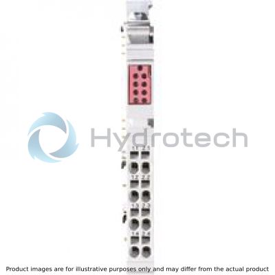
R-IBIL24DO8/HD-PAC
R911171973
I/O Rexroth Inline Digital: Output
BOSCH REXROTH
MATERIAL: R911171973
SUMMARY: I/O Rexroth Inline Digital: Output
Quantity in stock: 2
Quantity Details:- Hydrotech Stock: 0 can ship May 3, 2024
- Factory Stock: 2 can ship June 21, 2024
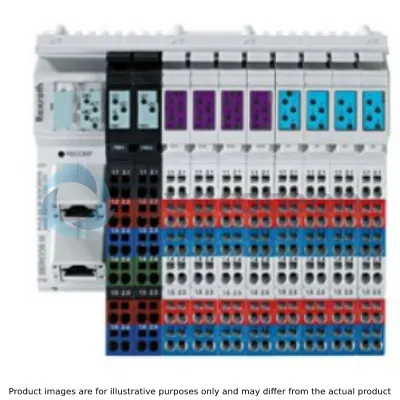
The Inline module is designed for use within an Inline station. It is used to output digital signals.
General data
|
Type |
R-IB IL 24 DO 8/HD-PAC | |
|
Color |
Gray | |
|
Weight 1) |
g |
60 |
|
Operating mode |
Process data operation with 1 byte | |
|
Ambient temperature (operation) |
-25 °C ... +55 °C | |
|
Ambient temperature (storage/transport) |
-25 °C ... +85 °C | |
|
Permissible relative humidity (operation) |
10 % ... 95 % acc. to DIN EN 61131-2 | |
|
Permissible relative humidity (storage/transport) |
10 % ... 95 % acc. to DIN EN 61131-2 | |
|
Air pressure (operation) |
70 kPa ... 106 kPa (up to 3000 m above sea level) | |
|
Air pressure (storage/transport) |
70 kPa ... 106 kPa (up to 3000 m above sea level) | |
|
Protection type |
IP 20, IEC 60529 | |
|
Protection class |
III, EN 61131-2, IEC 61131-2 | |
| 1) | Including plug |
Connection data
|
Type |
R-IB IL 24 DO 8/HD-PAC | |
|
Designation |
Inline connection plug | |
|
Connection type |
Spring-cage connection | |
|
Conductor cross-section solid/flexible/AWG |
0.08 mm² ... 1.5 mm² 0.08 mm² ... 1.5 mm² 28 ... 16 |
|
Interface local bus
|
Type |
R-IB IL 24 DO 8/HD-PAC | |
|
Connection type |
Inline data jumper | |
|
Transmission speed |
kBit/s |
500 |
Inline potentials/performance balance
|
Type |
R-IB IL 24 DO 8/HD-PAC | |
|
Logic voltage UL |
V DC |
7.5 |
|
Maximum current consumption from UL |
mA |
45 |
|
Maximum power consumption from UL |
W |
0.34 |
|
Segment supply voltage US |
V DC |
24 |
|
Current consumption from US |
A |
≤ 4 |
|
Power dissipation |
Max. 0.62 W | |
Digital outputs
|
Type |
R-IB IL 24 DO 8/HD-PAC | |||
|
Number of digital outputs |
8 | |||
|
Connection type |
Spring-cage connection | |||
|
Connectivity technology |
1-wire | |||
|
Description of the input |
EN 61131-2 type 1 and 3 | |||
|
Nominal output voltage UOut |
V DC |
24 | ||
|
Nominal input current at UIN |
mA |
2.4 | ||
|
Output current per channel |
mA |
≤ 500 | ||
|
Output current per device |
A |
4 | ||
|
Nominal load |
Ohmic |
48 Ω |
W |
12 |
|
Lamps |
W |
12 | ||
|
Inductance |
1.2 H; 50 Ω |
VA |
12 | |
|
Signal delay upon turning on of a |
Ohmic nominal load |
µs |
500 | |
|
Lamp nominal load |
ms |
100 | ||
|
Inductive nominal load |
1.2 H; 50 Ω |
ms |
100 | |
|
Signal delay upon deactivating a |
Ohmic nominal load |
ms |
1 | |
|
Maximum switching frequency for a |
Ohmic nominal load |
Hz |
300 | |
|
Lamp nominal load |
Hz |
8 | ||
|
Inductive nominal load |
Hz |
0.5 | ||
|
Behavior for overload |
Automatic restart | |||
|
Response time for ohmic overload (12 Ω) |
s |
≈ 3 | ||
|
Restart frequency for ohmic overload |
Hz |
400 | ||
|
Restart frequency for lamp overload |
Hz |
400 | ||
|
Behavior for inductive overload |
Output can be destroyed | |||
|
Response time upon short-circuit |
s |
≈ 1 | ||
|
Reverse voltage protection from short pulses |
Reverse voltage protection | |||
|
Resistance to permanently generated reverse voltage |
mA |
≤ 500 | ||
|
Behavior when the voltage is deactivated (power down) |
The output follows the power supply without delay | |||
|
Limited inductive cut-off voltage |
-15 V ≤ UDemag ≤ -45.8 V (UDemag = demagnetization voltage) | |||
|
Unique maximum energy when free-wheeling |
mJ |
300 | ||
|
Overcurrent cutoff |
A |
≥ 0.7 | ||
|
Output current in deactivated state |
μA |
≤ 300 | ||
|
Output voltage in deactivated state |
V |
≤ 1 | ||
Programming data
|
Type |
R-IB IL 24 DO 8/HD-PAC | |
|
ID code (hex) |
BD | |
|
ID code (dec) |
189 | |
|
Length code (hex) |
81 | |
|
Length code (dec) |
129 | |
|
Process data channel |
bits |
8 |
|
Input address room |
byte |
0 |
|
Output address room |
byte |
8 |
|
Parameter channel (PCP) |
byte |
0 |
|
Register length (bus) |
bits |
8 |
PROFIBUS telegram data
|
Type |
R-IB IL 24 DO 8/HD-PAC | |
|
Need for parameter data |
byte |
3 |
|
Need for configuration data |
byte |
4 |
Electrical isolation/insulation of the voltage ranges
|
Type |
R-IB IL 24 DO 8/HD-PAC | |
|
Separate potentials in the system of bus coupler/feed module and I/O module |
||
|
Test distance |
Test voltage | |
|
5 V supply incoming remote bus/7.5 V supply (bus logic) |
500 V AC, 50 Hz, 1 min. | |
|
5 V supply to further remote bus/7.5 V supply (bus logic) |
500 V AC, 50 Hz, 1 min. | |
|
7.5 V supply (bus logic)/24 V supply (peripherals) |
500 V AC, 50 Hz, 1 min. | |
|
24 V supply (peripherals)/function earth |
500 V AC, 50 Hz, 1 min. | |
Error messages to the higher-level control or computer system
|
Type |
R-IB IL 24 DO 8/HD-PAC | |
|
Error message |
Short-circuit/overload on the digital outputs; error message and display (2 Hz) via the LED (D) on the module | |
|
Approvals |
|
The current approvals can be found at www.boschrexroth.com. |

Dimensions
|
Type |
R-IB IL 24 DO 8/HD-PAC | |
|
A |
mm |
12.2 |
|
B |
mm |
120 |
|
C |
mm |
71.5 |
|
Note on dimensions |
The depth applies when using a support rail TH 35-7.5 (acc. to EN 60715). | |