
BOSCH REXROTH
R901460889
Connectors
ABCOC Customer oriented controlls
BOSCH REXROTH
MATERIAL: R901460889
SUMMARY: ABCOC Customer oriented controlls
Quantity in stock: 0
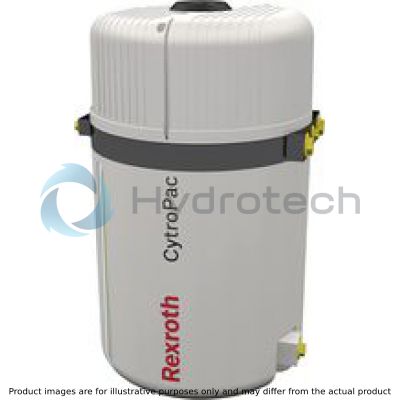
The compact revolution for hydraulic power units: completely equipped and integrated.
Rexroth has started the hydraulic power unit revolution. Lack of installation space is no longer a reason to go without hydraulic power: The new CytroPac power unit provides maximum power in the smallest space with everything you need for fast installation – including an economical Sytronix drive, completely wired frequency converter and Industry 4.0 compatibility. With powerful 4 KW and pressure of 240 bar in 50 percent less installation space. Furthermore, CytroPac also complies with the EU Ecodesign Directive 2009/125/EC. Simply connect power, fluid and interface and go. A small revolution!
Benefits:
Extremely compact Highly efficient Integrated Convenient Extra low-noise Sustainable Future-proof|
01 |
02 |
03 |
04 |
05 |
06 |
07 |
08 |
09 |
10 |
11 |
12 |
||||||||
|
CYTROPAC |
– |
1X |
/ |
20 |
/ |
AF |
/ |
2 |
/ |
/ |
/ |
1 |
/ |
7035 |
* |
|
Type |
||
|
01 |
Small power unit |
CYTROPAC |
|
Component series |
||
|
02 |
Component series 10 ... 19 (10 ... 19: unchanged installation and connection dimensions) |
1X |
|
Tank size |
||
|
03 |
20 liters |
20 |
|
Drive |
||
|
04 |
Asynchronous motor with frequency converter |
AF |
|
Performance class |
||
|
05 |
1.5 kW |
1,5 |
|
2.2 kW |
2,2 |
|
|
3.0 kW |
3,0 |
|
|
4.0 kW |
4,0 |
|
|
Pump |
||
|
06 |
Size 4 |
AS04 |
|
Size 5 |
AS05 |
|
|
Size 8 |
AS08 |
|
|
Size 11 |
AS11 |
|
|
Size 14 |
AS14 |
|
|
Operating pressure |
||
|
07 |
Maximum operating pressure 240 bar |
2 |
|
Sensor technology |
||
|
08 |
Basic |
B |
|
Advanced |
A |
|
|
Premium |
P |
|
|
Cooling type / maximum cooling power fluid |
1) |
|
|
09 |
Without |
WA |
|
700 Watt |
WB |
|
|
1400 Watt |
WC |
|
|
2000 Watt |
WD |
|
|
Filling |
||
|
10 |
Return flow filter |
1 |
|
Coloring |
||
|
11 |
RAL 7035 |
7035 |
|
Additional details |
||
|
12 |
Further details in the plain text |
* |
|
|
||
|
Notice: |
||
| 1) | The connection to a cooling water supply for cooling the motor and the frequency converter must always be ensured before the operation. |
|
Sensor and interface selection |
Basic |
Advanced |
Premium |
|
|
Sensor technology |
Filling level sensor early warning (10 liters) |
✔ |
✔ |
✔ |
|
Filling level sensor shut-off (13 liters) |
✔ |
✔ |
✔ |
|
|
Oil temperature sensor early warning (55 °C) |
✔ |
✔ |
✔ |
|
|
Oil temperature sensor shut-off (65 °C) |
✔ |
✔ |
✔ |
|
|
Filter contamination sensor early warning (75%) |
✔ |
✔ |
✔ |
|
|
Filter contamination sensor shut-off (100%) |
✔ |
✔ |
✔ |
|
|
Shut-off overtemperature of the drive unit |
✔ |
✔ |
✔ |
|
|
Analysis |
Wiring and evaluation of the sensor technology by machine control necessary |
✔ |
||
|
Wiring and evaluation of the sensor technology integrated in the power unit |
✔ |
✔ |
||
|
Read-out of all power unit parameters for condition monitoring |
✔ |
|||
|
Interfaces |
Input (24 V) enable power unit |
✔ |
✔ |
✔ |
|
Input (24 V) reset power unit |
✔ |
✔ |
✔ |
|
|
USB service interface |
✔ |
✔ |
✔ |
|
|
Output - power unit ready for operation (24 V); fault 0 V |
✔ |
✔ |
✔ |
|
|
Output - power unit early warning (24 V) |
✔ |
✔ |
||
|
Multi-Ethernet interface |
✔ |
|||
|
Functions |
Sleep function for accumulator charging circuit 2) |
✔ |
✔ |
✔ |
|
Up to four parameter configurations (e.g. pressure ratings) |
✔ |
✔ |
✔ |
|
|
Prestart Control 1) |
✔ |
✔ |
✔ |
|
|
Error visualization via LED strip |
✔ |
✔ |
||
|
Access to and adjustment of all power unit parameters (e.g. pressure ratings, flows) |
✔ |
|||
| 1) |
Prestart control: By means of a control signal, the drive unit is already accelerated before hydraulic actuators are connected. This reduces the collapse of pressure and you can possibly do without a hydraulic accumulator. |
| 2) |
Sleep function: By means of the integrated speed monitoring, the CytroPac is switched off in case of flows smaller than a set threshold value. This increases the energy efficiency and you can, for example, realize an accumulator charging circuit without additional control signals (see R911378635 Sytronix short instructions). |
For applications outside these parameters, please consult us!
general
|
Installation position |
vertical | ||
|
Line connections |
Pressure port |
G1/2 | |
|
Return flow |
G1/2 | ||
| G1 | |||
|
Place of installation |
Industrial building; stationary application | ||
|
Ambient temperature range |
(in case of operation) |
°C |
+10 … +40 |
|
Material |
Oil tank |
PA66 GF30 | |
|
Hood |
PA66 GF30 | ||
|
Central plate |
GG with corrosion protection | ||
|
Weight |
without oil |
kg |
60 ... 65 (depending on configuration level) |
| 1) | Return flow via filter |
| 2) | 2x, direct |
hydraulic
|
Maximum operating pressure |
bar |
240 | |
|
Maximum flow |
See characteristic curves | ||
|
Capacity fluctuation |
l |
10 | |
|
Tank capacity |
l |
20 | |
|
Maximum return flow |
via return flow filter |
l/min |
35 |
|
Hydraulic fluid temperature range |
°C |
+10 … +65 | |
|
Permissible hydraulic fluid |
see table below | ||
|
Maximum admissible degree of contamination of the hydraulic fluid 1) |
Cleanliness class according to ISO 4406 (c) |
Class 20/18/15 | |
|
Return flow filter |
Filter rating |
µm |
10 |
|
Cold start 2) |
°C |
< 10 | |
|
Early warning |
% |
75 | |
|
Shut-off |
% |
100 | |
|
Filling level monitoring |
Early warning |
l |
10 |
|
Shut-off |
l |
13 | |
|
Temperature monitoring |
Early warning |
°C |
55 |
|
Shut-off |
°C |
65 | |
|
Pump |
Minimum flow |
l/min |
1 |
|
Viscosity range of pressure fluid |
mm²/s 3) |
12 … 800 | |
|
mm²/s 4) |
20 … 100 |
| 1) | Cleanliness levels specified for the components must be maintained in the hydraulic systems. Effective filtration prevents malfunctions and simultaneously extends the service life of the components. |
| 2) | Maximum flow 10 l/min |
| 3) | Admissible range (maximum admissible start viscosity 2000 mm2/s) |
| 4) | Recommended range |
|
Hydraulic fluids |
Classification |
Suitable sealing materials |
Standards |
Data sheet |
|
Mineral oil |
HLP ISO VG 32 HLP ISO VG 46 |
NBR, FKM |
DIN 51524 |
90220 |
| 1) | For more information and data on the use of other hydraulic fluids please contact us. |
electrical
|
Performance class |
kW |
1.5 | 2.2 | 3 | 4 | |
|
Voltage |
(according to IEC 60038) |
V AC |
380 ... 480 (-15% / +10%) | |||
|
Frequency |
Hz |
50/60 | ||||
|
Protection class according to DIN EN 60529 |
IP 54 | |||||
|
Maximum pre-fuse protective motor switch |
(on the customer side) |
A |
10 | 16 | 20 | |
Cooling water
|
Requirement cooling water supply |
||
|
Flow |
l/min |
> 8 |
|
Inlet temperature |
°C |
+15 ... +25 |
|
Ports |
2x |
G1/2 |
|
Maximum glycol share |
% |
30 |
|
Maximum cooling water pressure |
bar |
30 |
Notice:
The cooling water supply for cooling the motor and the frequency converter must always be activated before the operation. It must be ensured that the cooling water supply temperature does not fall below the dewpoint of the ambient air of the power unit.
Different coolant possible after consultation.
(measured with HLP32, ϑOil = 40 ±5 °C; voltage 380V - 480V)
Performance diagram for the project planning of the performance class
Continuous operation (S1) 1.5 kW

|
1 |
1.5 |
kW |
|
2 |
2.2 |
kW |
|
3 |
3.0 |
kW |
|
4 |
4.0 |
kW |
Performance diagram for selecting the pump
Continuous operation (S1) 1.5 kW

|
1 |
4 |
cm3 |
|
2 |
5.5 |
cm3 |
|
3 |
8 |
cm3 |
|
4 |
11 |
cm3 |
|
5 |
14 |
cm3 |
Performance diagram for selecting the pump
Continuous operation (S1) 2.2 kW

|
1 |
4 |
cm3 |
|
2 |
5.5 |
cm3 |
|
3 |
8 |
cm3 |
|
4 |
11 |
cm3 |
|
5 |
14 |
cm3 |
Performance diagram for selecting the pump
Continuous operation (S1) 3.0 kW

|
1 |
4 |
cm3 |
|
2 |
5.5 |
cm3 |
|
3 |
8 |
cm3 |
|
4 |
11 |
cm3 |
|
5 |
14 |
cm3 |
Performance diagram for selecting the pump
Continuous operation (S1) 4.0 kW

|
1 |
4 |
cm3 |
|
2 |
5.5 |
cm3 |
|
3 |
8 |
cm3 |
|
4 |
11 |
cm3 |
|
5 |
14 |
cm3 |
Circuit diagram, hydraulic

|
1 |
Oil tank |
|
Electrical connections |
|
|
1.1 |
Heat exchanger |
|||
|
2 |
Pump |
a) |
Basic: |
|
|
3 |
Motor |
11 |
12X1: Feed-in |
|
|
4 |
Return flow filter |
12 |
15X1: M12x1 customer interface (enable) |
|
|
4.1 |
Filter contamination sensors |
13 |
14X1: USB service interface |
|
|
5 |
Float and oil temperature sensor |
|||
|
6 |
Breathing filter |
b) |
Advanced: |
|
|
7 |
Frequency converter |
14 |
16X1: M12x1 evaluation sensors (wired at the plant) |
|
|
8 |
Cooling package (option) |
|||
|
9 |
Optical oil level check and oil drain |
c) |
Premium: |
|
|
10 |
Pressure load cell |
15 |
21X1: Multi-Ethernet interface |
|

Feed-in
Feed-in including pre-fuse and mains contactor is to be realized on the customer side.

|
Voltage |
3P 380 ... 480 V AC (-15% / +10%) |
|
Frequency |
50/60 Hz |
|
Assignment |
L1/L2/L3/PE |
|
Rotating field |
Rotating field right |
|
Pre-fuse on the customer side |
Power 1.5 kW → maximum 10 A Power 2.2 kW → maximum 16 A Power 3.0 kW → maximum 20 A Power 4.0 kW → maximum 20 A |
USB to the frequency converter
Interface frequency converter (USB A-mini)

Filling level, temperature and filter contamination sensor

Notice:
In the "Basic" configuration level, the sensors have to be wired and evaluated on the customer side.
Allocation mating connector "Basic" (M12x1 on the customer side)

Notice:
If no Ready for operation → then Fault
Allocation mating connector "Advanced" and "Premium" (M12x1 on the customer side)

|
EX3 |
EX4 |
|
|
0 |
0 |
Parameter set 1 |
|
0 |
1 |
Parameter set 2 |
|
1 |
0 |
Parameter set 3 |
|
1 |
1 |
Parameter set 4 |
Notice:
If no Ready for operation → then Fault
In the "Advanced" and "Premium" configuration level, the sensors are wired with the integrated control and evaluated at the factory.
The sensor conditions are signaled via the integrated LED strip and can be read out via the USB service interface.

Notice:
The power unit must be set up on a level area, preferably on a damping mat.
For the fastening of the power unit, a fastening set (see Accessories) is available.
|
Pump version |
AS04 | AS05 | AS08 | AS11 | AS14 | ||
|
ØD |
mm |
366 | |||||
|
H1 |
mm |
610 | |||||
|
X |
Port P |
mm |
65 | 64 | 61 | 58 | 57 |
|
D1 |
G1/2 | ||||||
|
H2 |
mm |
405 | |||||
|
D2 |
G1 | ||||||
|
B1 |
mm |
130 | |||||
|
D3 |
G1/2 | ||||||
|
D4 |
G1/2 | ||||||
|
B2 |
mm |
130 | |||||
|
A1 |
mm |
63.5 | |||||
It has to be ensured before the commissioning that on the customer side, a pressure relief valve (set pressure 10% over nominal pressure, however at most 260 bar) has been installed in the pressure line. The feed-in and 24 V supply must be secured on the customer side, as described under “Electrical connection”. For the cooling of the motor and the frequency converter, the power unit must imperatively be connected to cooling water. The connection of the power unit to the machine must be realized by means of hydraulic hoses (no rigid pipeline admissible). It must be ensured on the customer side that the cooling water supply temperature does not fall below the dewpoint of the ambient air of the power unit. The maximum operating pressure of 240 bar must not be exceeded.
Read-in and read-out of the power unit parameters
The Rexroth EFC 5610 frequency converter is integrated into the CytroPac; this frequency converter can be connected to an external computer by means of a mini USB cable.
Access to and setting of the frequency converter is possible by means of the ConverterWorks software. The software can be downloaded at the website www.boschrexroth.de.
Changing the operating pressure:
Connect the power unit to the voltage supply. Open the ConverterWorks software on an external computer Connect the CytroPac to an external computer, using a mini USB cable and interface 14X1 The software will automatically establish a connection to the power unit (if not, click Tools → Connect/Switch online) The control pressure can be changed using parameter F1.05 in the parameter editor.
The operating instructions R912006684 contain further information on the handling of the frequency converter. You can also download this document at www.boschrexroth.de.
Fittings
|
Material number |
Denomination |
|
|
R901460961 |
CONNECTION SET HYDR.CON*OPT.CYTROPAC |
|
|
Comprising: |
||
|
▶ Cooling connection |
2x R900006158 |
MALE CONNECTOR 24SDS-E-C-18L-G1/2-S& (ZN1101-1/11) |
|
▶ Pressure line connection |
1x R900762671 |
MALE CONNECTOR 24SDS-E-S-18L-G1/2-S& (ZN1101-1/11) |
|
▶ Return flow connection via filter |
1x R900006158 |
MALE CONNECTOR 24SDS-E-C-18L-G1/2-S& (ZN1101-1/11) |
|
▶ Return flow connection G1 |
2x R913011613 |
SCREW PLUG ZN10001-G1A-F-ST |
Mating connector
|
Material number |
Denomination |
|
R901460889 |
PLUG-IN CONNECTOR 0DEG *OPT.CYTROPAC |

|
B1 approx. |
B2 |
SW |
ØD |
|
mm |
mm |
mm |
mm |
| 78.5 | 19.5 | 27 | 34.6 |
Filling coupling
|
Material number |
Denomination |
|
R901460916 |
CHARGING DEVICE MD-012-2*OPT.CYTROPAC |
Filter element
|
Material number |
Denomination |
|
R928035258 |
35.0035CP H10XL-R00-0-M |
Foot mounting
|
Material number |
Denomination |
|
R901460890 |
FASTENING KIT BASE285 *OPT.CYTROPAC |

 Tank mounting at central plate with 1x hexagon socket head cap screw M6 x 430 mm (included in the scope of delivery) Foot mounting with 4x hexagon socket head cap screw M8 x 20 mm (not included in the scope of delivery)
|
ØD1 |
ØD2 |
ØD3 |
|
mm |
mm |
mm |
| 285 | 162 | 9 |