
BOSCH REXROTH
R190225200
All Other Products
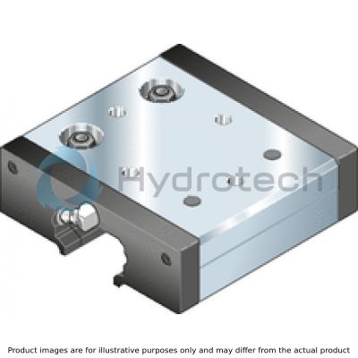
Cam Roller Guides Blocks Size 052
BOSCH REXROTH
MATERIAL: R190225200
SUMMARY: Cam Roller Guides Blocks Size 052
Quantity in stock: 1
Quantity Details:- Hydrotech Stock: 0 can ship May 6, 2024
- Factory Stock: 1 can ship July 8, 2024
Technical data
|
Size |
20 | 25 | 32 | 52 | 52-h | 52-sh | |
|
Fy max 1) |
N |
700 | 1000 | 2500 | 4500 | 8000 | |
|
F0y max 1) |
N |
700 | 1000 | 2500 | 4500 | 8000 | |
|
Fz max |
N |
400 | 850 | 1500 | 2400 | 4800 | |
|
F0z max |
N |
600 | 660 | 1400 | 2500 | 4000 | 7900 |
|
Mx max |
Nm |
3,2 | 3,8 | 11 | 32 | 50 | 101 |
|
M0x max |
Nm |
4,8 | 6 | 18 | 52 | 84 | 166 |
|
My max |
Nm |
6,8 | 9 | 26 | 45 | 126 | 288 |
|
M0y max |
Nm |
10,2 | 15 | 42 | 75 | 210 | 474 |
|
Mz max |
Nm |
12 | 16 | 30 | 75 | 236 | 480 |
|
M0z max |
Nm |
12 | 16 | 30 | 75 | 236 | 480 |
|
vmax 2) |
m/s |
10 | |||||
|
amax |
m/s² |
50 | |||||
|
Temperature stability |
-20 °C ... +80 °C | ||||||
|
Weight |
kg |
0.2 | 0.25 | 0.56 | 1.5 | 2.6 | 3.3 |
| 1) | Observe the permissible lateral force of the guide rail (see notes for mounting). |
| 2) | For average load. |
| Attention: Not to be used for the life expectancy calculation! | |
| For service life calculations use the load ratings and moments given in the tables for service life calculations. |
Load ratings and moments for calculating the service life
|
Size |
20 | 25 | 32 | 52 | 52-h | 52-sh | |
|
Cy |
N |
2300 | 2550 | 7335 | 17150 | 27900 | 31000 |
|
C0y |
N |
1600 | 1780 | 4560 | 10200 | 15400 | 18200 |
|
Cz |
N |
1336 | 1357 | 4300 | 10050 | 16775 | 18400 |
|
C0z |
N |
783 | 803 | 2200 | 4900 | 7630 | 8750 |
|
MX |
Nm |
10,7 | 13 | 56 | 211 | 352 | 390 |
|
M0x |
Nm |
6,3 | 7,6 | 29 | 103 | 160 | 184 |
|
My |
Nm |
22,7 | 30,5 | 129 | 301 | 880 | 1100 |
|
M0y |
Nm |
13,3 | 18 | 66 | 147 | 400 | 520 |
|
Mz |
Nm |
39 | 57 | 220 | 515 | 1465 | 1860 |
|
M0z |
Nm |
27 | 40 | 137 | 306 | 808 | 1100 |
| Observe maximum permissible loads due to forces and moments as shown in the "Technical data” table! |
Legend
|
Symbol |
Description |
Unit |
Picture |
|
Cy |
Dynamic load capacity in y-direction |
N |
 |
|
C0y |
Static load capacity in y-direction |
N |
|
|
Cz |
Dynamic load capacity in z-direction |
N |
 |
|
C0z |
Static load capacity in z-direction |
N |
|
|
Fy max |
Maximum dynamic load in y-direction |
N |
|
|
F0y max |
Maximum static load due to a resulting force in the y-direction |
N |
|
|
Fz max |
Maximum dynamic load in z-direction |
N |
|
|
F0z max |
Maximum static load due to a resulting force in the z-direction |
N |
|
|
Mx max |
Maximum permissible dynamic torsional moment about the x-axis |
Nm |
 |
|
M0x max |
Maximum permissible static torsional moment about the x-axis |
Nm |
|
|
My max |
Maximum permissible dynamic torsional moment about the y-axis |
Nm |
 |
|
M0y max |
Maximum permissible static torsional moment about the y-axis |
Nm |
|
|
Mz max |
Maximum permissible dynamic torsional moment about the z-axis |
Nm |
 |
|
M0z max |
Maximum permissible static torsional moment about the z-axis |
Nm |
|
|
vmax |
Maximum permissible speed |
m/s |
|
|
amax |
Maximum acceleration travel |
m/s2 |
|
|
MX |
Dynamic torsional moment about the x-axis |
Nm |
|
|
M0x |
Static torsional moment about the x-axis |
Nm |
|
|
My |
Dynamic torsional moment about the y-axis |
Nm |
|
|
M0y |
Static torsional moment about the y-axis |
Nm |
|
|
Mz |
Dynamic torsional moment about the z-axis |
Nm |
|
|
M0z |
Static torsional moment about the z-axis |
Nm |
Rigidity
An increased rigidity can be achieved with higher pre-tensioning force by using eccentric setting.
Acceleration
High accelerations are permitted if slippage is avoided. For this, the pre-tensioning force FV by increasing the eccentric setting; see diagram.
Attention: The maximum permissible load is reduced by the increase of the pre-tensioning force.

| 1) | Permissible range |
| 2) | a = acceleration |
| 3) | Fv/Cy = standard setting |

| 1) | Eccentric setting |
| Lube nipples | |
| Sizes 20 – 32: | |
| - Funnel-type lube nipple | |
| - Form B - thread M3 | |
| Sizes 52 – 52-sh: | |
| - Hydraulic-type lube nipple | |
| - BM 6 DIN 71412 | |
| Connection possible on two sides. |
Dimensions
|
Size |
20 | 25 | 32 | 52 | 52-h | 52-sh | |
|
A |
mm |
56 | 65 | 86 | 130 | 145 | 155 |
|
B |
mm |
79 | 95 | 112 | 136 | 186 | 205 |
|
B1 |
mm |
59 | 75 | 92 | 104 | 154 | 173 |
|
B2 |
mm |
7 | 16 | ||||
|
E1 |
mm |
39 | 50 | 59 | 90 | 105 | 115 |
|
E2 |
mm |
49 | 60 | 70 | 110 | 140 | |
|
E3 |
mm |
34 | 40 | 54 | 83.3 | 90 | 95 |
|
E4 |
mm |
34 | 45 | 60 | 105 | 120 | |
|
E5 |
M5 | M8 | M10 | M12 | |||
|
H |
mm |
22 | 25 | 35.5 | 54.3 | 60.4 | |
|
H1 |
mm |
8.5 | 9 | 13 | 19.4 | 24 | |
|
H2 |
mm |
13 | 14.4 | 20.5 | 29.2 | 35.3 | |
|
H3 |
mm |
20 | 22.3 | 29.5 | 42.2 | 51 | |
|
SW1 |
mm |
7 | 10 | 16 | 18 | ||
|
SW2 |
mm |
2 | 3 | 4 | 6 | ||
|
SW3 |
mm |
2 | 4 | 6 | 8 | ||
Centric pins are already tightened when delivery.